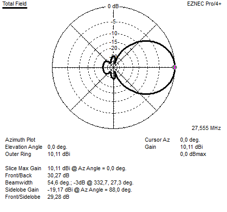
Above the freespace azimuth plot
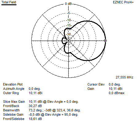
Above the freespace elevation pattern
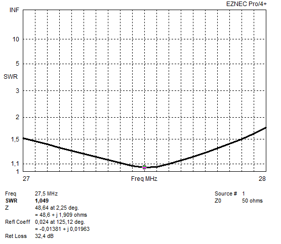
Above the SWR diagram
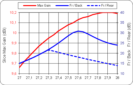
Above the Gain, Front to back and Front to rear response versus frequency.
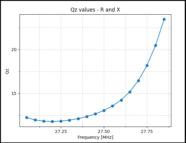
Above the antenna Q-factor over 1 MHz.
(If the Q factor is below 15 over a wide range of frequencies above and below the operating band, these
are very good stable antennas.
Q factors between 15 and 30 over a wide range of frequencies above and below the operating range
represent acceptable values for slightly less stable antennas.
Q factors between 30 and 50 indicate that they are relatively unstable antennas, although often in some
narrow part of the range they can have a lower Q factor.
Q factors over 50, regardless of the possible narrow parts of the lower Q band, represent extremely
unstable antennas. (SOURCE: YU1AW) )
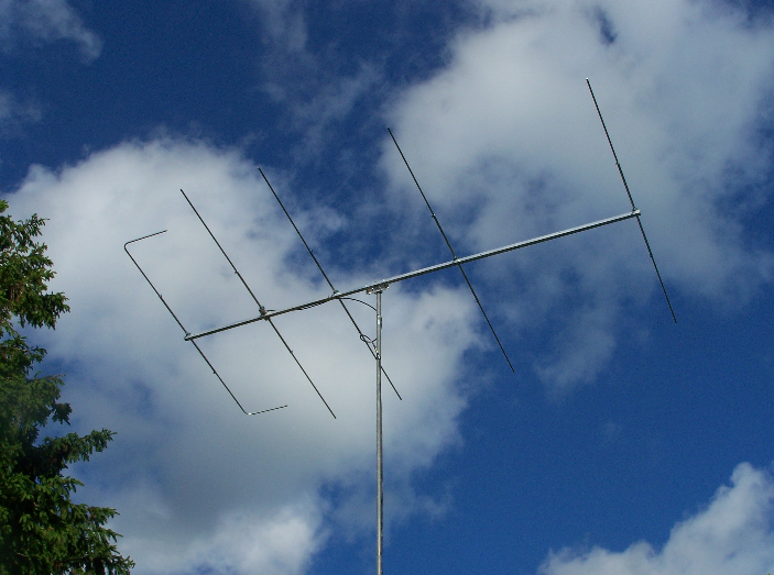
For: DX portion 11 meter band
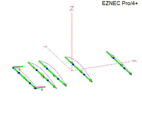
Antenna Type: 5el U-YAGI
Bend reflector (UA9TC/G6XN)
Designed by: 19DX348 17-5-2014
Boom length: 7,07 Meter
Gain: 10,11 dBI (@27,555 MHz)
FB <30,27 dB (H field)
FR <29,28 dB (H field)
Impedance: 50 Ohms, direct fed
SWR 2:1 > 1300 KHz.
SWR 1:1,1 > 250 KHz.
ELEMENT DIMENSIONS:
ELEMENTS DIAMETERs ARE: 22mm and 18mm in diameter.
The center part of the element is 2 meter long and is made from the 22mm diameter tubing. And the 18mm is for the rest of the element lenght.
Do not change diameters, if you need other dimensions, or if you want to scale this antenna to another frequency..
Please feel free to ask !
ELEMENT: DISTANCE LENGHT: TIPS:
REFLECTOR 0,0 4,020 0,748
RADIATOR 1,325 5,266
DIRECTOR 1 2,105 5,116
DIRECTOR 2 4,050 5,054
DIRECTOR 3 7,070 4,674
FEEDING THE ANTENNA:
The impedance of the antenna is 50 Ohms and direct feed can be applied.
It is a must to always use A RF choke or 1;1 balun for any Yagi.