The RF choke here is based on work done by: G0TXQ
(Sadly Steve passed away in 2018, but left us with a wealth of usefull information.)
Thank you for all Steve !
(His site (thankfully) still can be reached here: http://www.karinya.net/g3txq/ )
A rf-choke is a device which “deals/chokes” with the common-mode currents.
In short:
Most of us, use coax cable to bring the signal to and from the antenna.
That coax cable is by definition an unbalanced feed line, logical cause the inner diameter isn’t equal to the outer diameter…not equal…hence not balanced.
A dipole for example, is a (or should be) balanced antenna both sides are equal.
(if the coax runs in a 90 degree angle and we are on the resonant frequency and the antenna is “free’ etc.)
So in many situations we are going from a un-balanced feed line over towards a balanced antenna.
In cases like these there could be a common-mode currents, this is also the true if we go from an unbalanced antenna to a unbalanced feedline.
Like we do in 99 percent of the cases with our vertical antennas.
A dipole at least has two equal parts, most verticals dont.
The half wave end-fed (Antron 99/GPA etc) is missing its counter part,
the 5/8 wave never has 5/8 wave length radials etc..
All those antennas are by definition not balanced.
Or simply there isnt balance in your antenna system because it isnt positioned entirly free but near obstacles which could shift the balans of the antenna etc.
In those cases we could have those common mode currents.
Those currents run back on the outer shield of the coax and could cause trouble like:
The SWR can be influenced, it COULD enhance NOISE ! it may cause QRM the antenna pattern could be skewed, gain might drop etc.
Sometimes you can actually notice it really clear, and sometimes you might not notice it.
It is hard to realise you have 3dB additional noise for the average CB user.
I mean we all hear the noise level rise as soon as we connect the antenna to the tranceiver.
Perhaps, that makes the RF-choke somewhat a mistery.
One could look at it like a seatbelt, you can drive without…but it could be helpfull if things go wrong !
In order to illuminate those currents one could place a device called a RF-choke.
Nice to know: Delta loops, quads and folded dipoles or other full wave antennas have less issues with common mode currents.
This is because full wave loops have a high common mode impedance at the feedpoint, ill try to explain that in a future article.
(this maybe one reason why some people think a full wave loop is quieter, it was one of te reasons i often used folded dipole yagi’s….
But up front…a good balun on any traditional yagi will solve that possible issue).
WHAT SIZES ?
This is based on steve his work and derived from :
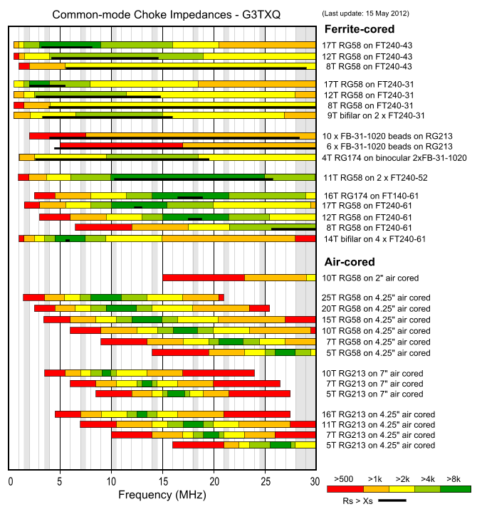
From this we can see:
For our 27 MHz 4 or 5 turns gives a choke impedance well over thousands of ohms. (more then sufficient) If we look at the “green” bar (where the choke impedance is highest) we can see it shifts down in frequency when the number of turns become higher, and with less turns the frequency goes up.

So please do not use other diameters or number of turns… and yes it is raher critical…
MISTAKES WITH INSTALLATION !
The RF choke as described above is rather critical, it has a narrow bandwidth (compared to ferriet wound).
And mistakes are easily made which will reduce the effect !
The most common mistake would be that people tend to tape that RF CHOKE to a boom or metal mast, this is wrong.
A RF-Choke is a coil and thus acts like one. As soon as metal is attached to it’s values will change.
So just leave it hanging a few inches away from any metal objects.
Another mistake would be when you use the RF-Choke combind with a vertical without radials (Antron 99 / Imax etc).
An place the RF choke directly under the antenna, this is wrong.
You should place the RF choke 1 meter below the feedpoint.
As all verticals (including 1/2 waves endfed) need somekind of counterpoise, often this is the mast or coax.
When you place the RF-choke directly under the feedpoint performance actually could go down.
MEASUREMENTS ?
If you want to measure the Choke impedance, buy a VNA. (They are rather cheap these days !) Lots of fun ! Just make sure your measurement is correct.
Measuring something is easy to know if your measurments are correct that is another thing. With a VNA you can see how much “impedance” your choke actually has.
If you want to measure if there are common mode currents along your transmission line:
It is actually rather easy to construct a measuring device yourself. There are many circuit diagrams on the internet with just a couple components (really just a couple).
An example can be found here : http://www.ifwtech.co.uk/g3sek/clamp-on/clamp-on.htm
Finally:
Yes..there are other ways to deal with those common mode currents, a choke balun for example and others.
All will do about the same job… for a single band use like 27MHz the described RF-choke is a very good solution….
Anyway….
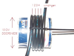
RG213… 4..5 turns 10cm diameter..leave it hanging dont tape it to metal…and you are good to go !
References: Common-mode chokes by G3TXQ
Welkom op de home page van TeTech by PA3DJS