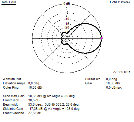
Above the freespace azimuth pattern EZNEC NEC 5 calculation
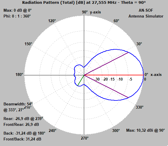
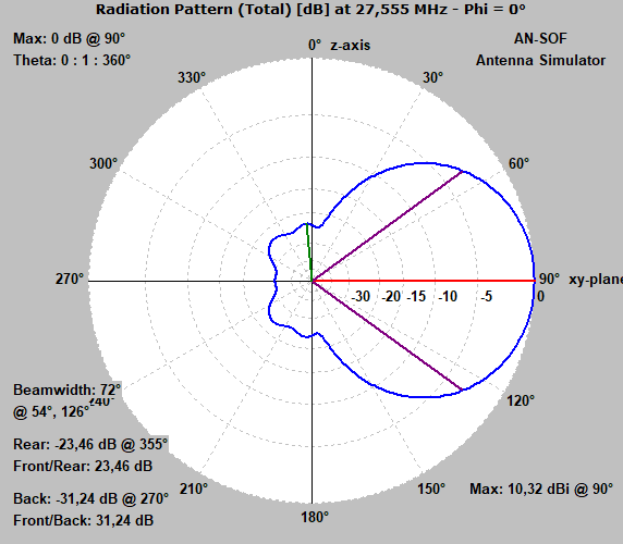
Above the freespace azimuth patten confirmation with AN-SOF
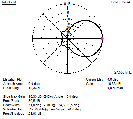
Above the freespace elevation pattern.
Above the freespace elevation pattern confirmation with AN-SOF
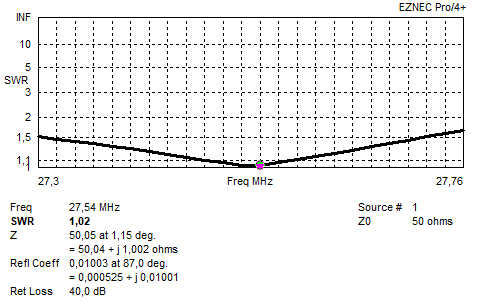
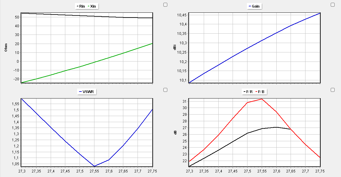
Above the SWR diagram
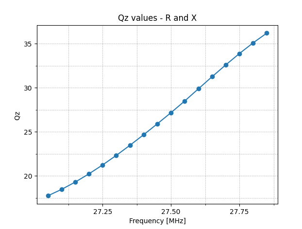
Above the antenna Q-factor
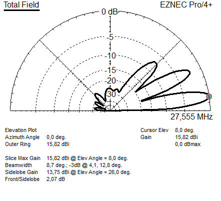
Above the elevation pattern when situated 18 meters above average ground conditions.
Above the antenna parameters produced by AN-SOF elevation and azimuth
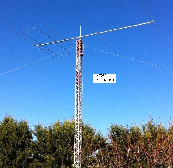
SPECIFICATION:
For: DX portion 11 meter band
Antenna Type: 5 el LFA YAGI
Designed by: G0KSC modified for 27 MHz by 19DX348 Jan 2016
Boom length: 7,47 Meter
Gain: 10,33 dBI (@27,555 MHz)
FB <30 dB (H field)
FR <23 dB (H field)
Impedance: 50 Ohms.
SWR 2:1 > 750 KHz.
SWR 1:1,1 > 100 KHz.
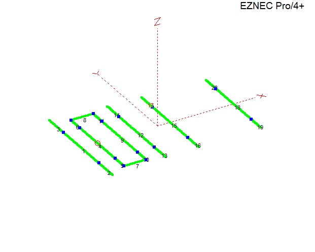
ELEMENT DIMENSIONS:
ELEMENTS DIAMETERS ARE:
22 mm and 18 mm and 14mm in diameter.
The center part of the element is 3,0 meter long and is made from the 22 mm diameter tubing.
The 18mm is for the rest of the element lenght.
The 14mm parts are inserted in the end of both radiatiors to make it a loop.
Do not change diameters, if you need other dimensions, or if you want to scale this antenna to another frequency..Please feel free to ask !
(You can not model these kind antennas with traditional Mininec and NEC2 software. We have designed these antenna with the best availible MoM/CMoM engines)
ELEMENT: DISTANCE LENGHT:
REFLECTOR 0,000 5,496
RADIATOR 1 0,800 4,510
RADIATOR 2 1,890 4,510
Director 1 2,720 5,110
Director 2 4,360 5,090
Director 3 7,470 4,950
FEEDING THE ANTENNA :
The antenna is 50 Ohms, the feedpoint is the radiator element closest to the reflector. A 1;1 balun is a must !
For more information about the LFA antenna please visit G0KSC his website.