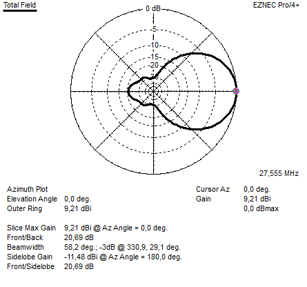
Above the freespace azimuth plot
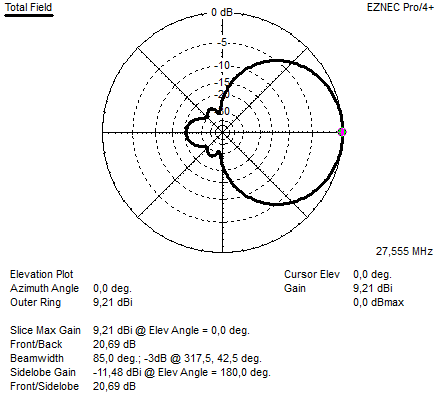
Above the freespace elevation plot
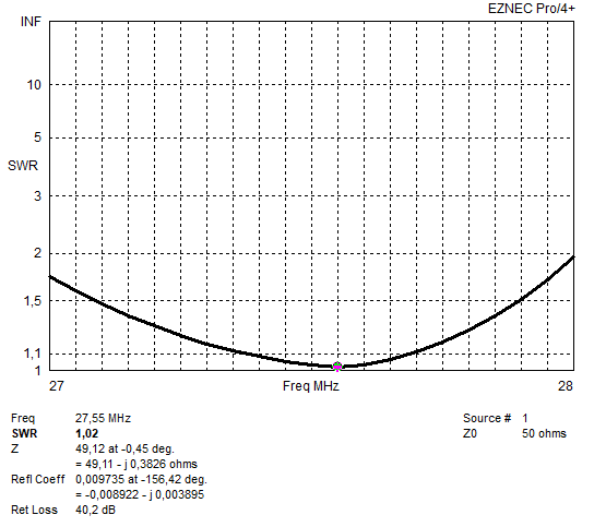
Above the SWR diagram
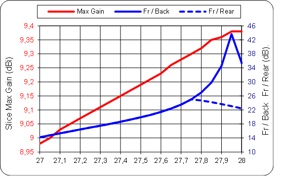
Above the Gain and Front to back and Front to rear versus frequency
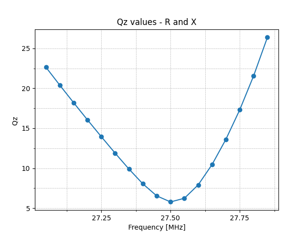
Above the calculated Q-factor.
If the Q factor is below 15 over a wide range of frequencies above and below the operating band, these
are very good stable antennas.
Q factors between 15 and 30 over a wide range of frequencies above and below the operating range
represent acceptable values for slightly less stable antennas.
Q factors between 30 and 50 indicate that they are relatively unstable antennas, although often in some
narrow part of the range they can have a lower Q factor.
Q factors over 50, regardless of the possible narrow parts of the lower Q band, represent extremely
unstable antennas. (SOURCE: YU1AW)
SPECIFICATION:
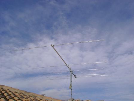
For: DX portion 11 meter band
Antenna Type: 4 el LFA YAGI
Designed by: G0KSC modified for 27 MHz by 19DX348 Jan 2016
Boom length: 5,17 Meter
Gain: 9,21 dBI (@27,555 MHz)
FB <20,69dB (H field)
FR <20,69 dB (H field)
Impedance: 50 Ohms.
SWR 2:1 > 1000 KHz.
SWR 1:1,1 > 300 KHz.
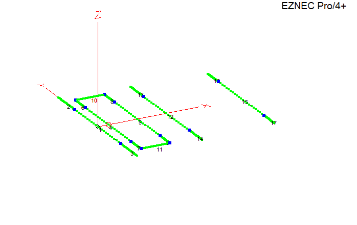
ELEMENT DIMENSIONS:
ELEMENTS DIAMETERS ARE: 20mm and 16mm in diameter. The center part of the element is 3,2 meter long and is made from the 20mm diameter tubing. And the 16mm is for the rest of the element lenght.
Do not change diameters, if you need other dimensions, or if you want to scale this antenna to another frequency..
Please feel free to ask !
ELEMENT: DISTANCE LENGHT:
REFLECTOR 0,000 5,606
RADIATOR 1 0,380 4,586
RADIATOR 2 1,425 4,586
Director 1 2,470 5,110
Director 2 5,170 4,730
FEEDING THE ANTENNA :
The antenna is 50 Ohms, the feedpoint is the radiator element closest to the reflector. A 1;1 balun is adviced !
For more information please visit G0KSC his website.